Computer-Aided-Design (CAD) 2
Laser Cutting Tutorial 2
Making a handphone stand 25 October 2021
To create a handphone stand using Fusion 360

To design a handphone stand using parametric, we have to set up user parameters for the dimension of the product such that if we want to change to dimension of it we can just change it in the change parameters instead of redesigning the whole thing which would take alot of time.
-Device height
-Device width
-Device thickness
-Material thickness
-Border (tray that holds the handphone)
-Angle (angle of the handphone lays on the stand)


Second line as device thickness + (material thickness x 3)
 Select the line function and draw a trapezium to be the leg
Third line as 20 mm


Set the dimension of the 2 lines (material thickness x 3)


Create new component and name it as tray


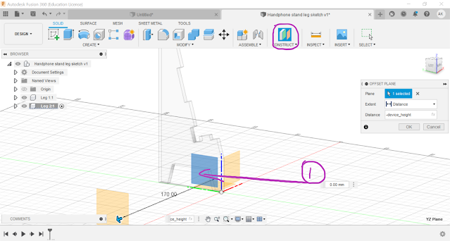
Create sketch and select the plane highlighted in purple


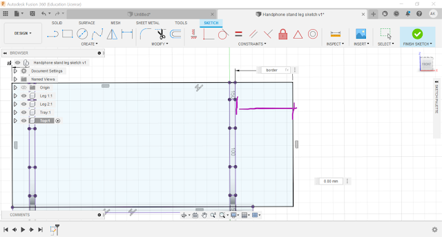
Draw a rectangle using the 2-point rectangle amd using the colinear constraint, select the 2 lines highlighted in purple and 2 lines highlighted in orange


Create new component and name as support

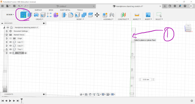
Create sketch and select the plane just created


Fillet all inner sharp edges by 0.1 mm and outer sharp edges by 5 mm

Reflection
After learning how to design using parametric construction in fusion 360, we were tasked to parametrically design a handphone stand using fusion 360. At the start, i found it difficult to follow the tutorial video or i was just following blindly as i still did not understand some of the functions of the fusion 360 and was not entirely clear of how exactly to parametric construct the handphone stand. However, as i slowly followed the guidance of the video, i started to understand more of the functions and shortcuts such as the dimension tool where i can easily change any length or angle of the line to a set value or a pre-set parameters. When i completed the handphone stand, i got a greater hang of the use of fusion 360 learning many different functions such as construct offset plane and understanding the use of certain constraints that can allow me to adjust my design much easier.
This tasks is important as it allowed us to use the refresher foundation that we had when designing a keychain and applied it to design a handpone stand while at the same time building more on the foundation of fusion 360. In this case, it was mainly focused on the concept of parametric construction. Parametric construction is very important in fusion 360 design as it allows the user to change the parameter and dimension of the design easily using the change parameter tool instead of having to painstakingly redesigning the whole thing again which allows to save time during the design phase. This task is also useful in the project in CP5070 as later down the road, we would to make a prototype of our product using laser cutting and 3D printing. When we want to change the dimension of the prototype, we would then be able to easily change the design in fusion 360 using parametric construction.
When i first learnt about parametric construction, i did not understand how the concept of it works and used to think that it was very difficult and i would rather redesign the whole thing in fusion 360. However, by going through this activity on designing a handphone stand, now i think that parametric construction is actually not that difficult and is very beneficially to have when designing in fusion 360. So next i will try on my own to design some products in fusion 360 using parametric construction to further improve my computer aided design skill.

Comments
Post a Comment