Laser Cutting
Laser Cutting Practical 28 October 2021
Improved Standard Operating Procedure (SOP) (Endorsed in blue)
A: Safety
1. Remove any foreign objects around the neck/body to prevent getting tangled into the Machine
2. Ensure long hair/ fringe is tied up
3. Lift the cover of the Laser Cutter fully
4. Do not put your head inside the machine
5. Do not slam the cover of the machine (as the interlocking light would disappear)
6. Do not assume LED is spoiled, ensure both Left and Right LED is green/on (See Figure 1)
7. Do not lean your body on the cover of the Laser Cutter (as it would trigger the safety interlock and operation of the Laser Cutter would halt)
8. Do not stare into the beam while cutting
9. Do not leave machine unattended while cutting/engraving
10. If a small fire occurs attempt to extinguish by blowing/removing material from laser cutter *Safety Feature: (There is a safety interlock, simply open the Laser cutter cover fully which will aid to stop the beaming of the laser and movement of the head)
11. If the material cannot be cut through, stop and check - Focus lens might be dirty.
* Continued use of dirty lens will result in Cracked Lens (See Figure 2)
12. When using the Epilog Software - Remember to on ‘Air Assist’ (if not it will result in Fire)
B. Start up
1. Turn on the air compressor (See Figure 3 and 4)
For Fusion Pro, air compressor is built into the fume extractor
2. Turn on the fume extractor (See Figure 5 and 6)

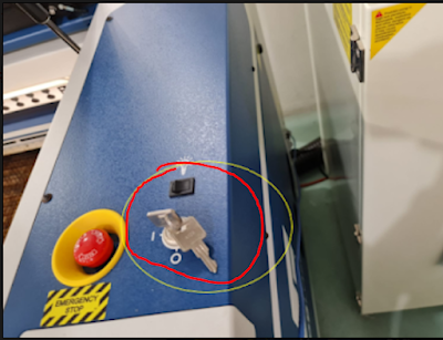
3. Turn on the main laser cutter (See Figure 7)
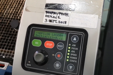
4. Wait until the laser cutter completes initializing [around 1 minute] (See Figure 8)
5. Proceed to the Workstation i.e., Desktop connected to Laser Cutter
C. Operation (Using CorelDraw):
*For Basic Features, Refer to Figure 9-12, (See Note below Figure 12 for guidance)
1. File -> Import; Import the DXF file (Fusion 360 File) into CorelDraw
2. Select the Image after Imported (See Figure 13)
3. Click Bottom Right Corner (Pen and Fill icon) and adjust the appropriate settings i.e. (Colour, Line weight and Fill) for Cutting and Engraving. (See Figure 12)
4. Once done, Press ‘Control +P’, Print box would pop-up, and Select ‘Print’ (See Figure 14)
Page Automatically updates to Epilog Software
(To change the dimension, it can be done in coreldraw by highlighting the part followed by grouping it together using 'Control + G' and typing in the dimension in the top bar)
D. Operation (Using Epilog Software)
1.Fusion Pro
1. Set ‘Autofocus’ -> ‘Thickness’ *Default is off (See Figure 15)
2. On the right-hand side, it will show the process of each object’s action which was pre-set earlier when using CorelDraw. Click on each process’s action to check the settings again. (See Figure 16)
*Note: Any object’s line-weight set as hairline are considered as vector and with thickness is considered as engraving
2.Fusion M2
1. Set ‘AutoFocus’ -> ‘On’
2. Choose ‘Air Assist’ -> ‘On’ for each process
(For Steps 1 & 2 See Figure 17)
3. On the right-hand side, it will show the process of each object’s action which was pre-set earlier when using CorelDraw. Click on each process’s action to check the settings again. (See Figure 18)
*Note: Any object’s line-weight set as hairline are considered as vector and with thickness is considered as engraving
E. Material Setting
1. Load Material Library
1. Click the ‘Folder Icon’ (See Figure 19) to Load Material Library
*Note: (See Figure 20 for view of Loaded Material Library)
2. Once Material Library has loaded, choose which material to be used for cutting/engraving. Do it for both Processes. Then Click ‘Import’ (See Figure 21)
3. For Engraving, Select the Engraving Tab and enter the thickness of the material chosen. (See Figure 22)
*Note: To be able to select a material, you would need to know its thickness so measure its thickness using a Vernier caliper first
4. For Cutting, Select the Vector Tab and enter the thickness of the material chosen. [i.e. Repeat Step 3]
5. Always Check that ‘Air Assist’ is turned on for FUSION M2 Machine (See Figure 22 – Blue Circle)
*Refer to Figure 23 for Final Adjustments for Machine in this step.
*Get laser cutter speed and power information to laser cut different materials and set in the settings
F. Positioning (*If required)
1.Fusion Pro
1) Adjust the position of the material using the build in camera in fusion Pro. (See Figure 24)
2.Fusion M2
*There is no Built-in camera
1) Adjust the material using mouse tool on the left bar and adjust base on the location of 2 ruler on the top and left. (See Figure 25)
G. Print
Once done, Click on “PRINT” to send file to Laser cutter. It will not cut immediately but to show up on the LCD screen instead. (See Figure 26)
1.Fusion Pro: To cut, check file name and estimated time to cut on the LCD touch screen. Once confirm, press the “play button” (See Figure 27)
2.Fusion M2: To cut, check file name and estimated time to cut on the LCD touch screen. Once confirm, press the “Go button” (See Figure 28)
Wait for 1 minute after completed cutting
H. Shut Down: (Reverse of Start up)
1. Turn off the main laser cutter (See Figure 7)
2. Turn off the fume extractor (See Figure 5 and 6)
3. Turn off the air compressor (See Figure 3 and 4)
I: Appendix
1. Safety:

Figure 1: Observe for Left and Right LED with Green light

Figure 2: See Cracked Lens
2. Start up:

Figure 3: Air Compressor

Figure 4: On Switch for Air Compressor
![]()

Figure 5: Perspective of where Fume Extractor is Located
– Downwards, Left-Hand side of Machine (see arrow)


Figure 6: Turning on Fume Extractor - Press Green Button
![]()

Figure 7: Switching on the main Laser Cutter

![]()
![]()
Figure 8: Wait for Initialization to Complete
3. Operation (Using CorelDraw)

Figure 9: Basic Features of CorelDraw

Figure 10: (1): Top Bar Icons and Description

Figure 11: (2): Side Bar Icons and Description

Figure 12: (3): Bottom Bar Icons and Descriptions
**Note: Vector Cut refers to outline of Shape to be cut, Engrave refers to fill of shape to be engraved, Engrave Etch/Score refers to outline of shape to be engraved

Figure 13: Selecting Drawing
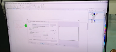
Figure 14: Select ‘Print’
4. Operation (Using Epilogue Software)
![]()

Figure 15
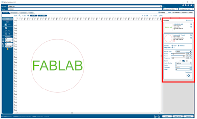
Figure 16
![]()
![]()

Figure 17

Figure 18
5. Machine Setting

Figure 19: Folder Icon which loads Material Library

Figure 20: Loaded Material Library Box

Figure 21: Loaded Material Library to select thickness & type of Material to be used

Figure 22

Figure 23: Final Adjustments for Machine
6. Positioning

Figure 24
Figure 25
7. Printing

Figure 26

Figure 27


Figure 28
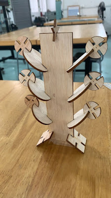
Laser Cut Pieces:
Individual Competency Test:


At first, I
found the practical a little challenging, as laser cutting and fusion 360 to
design a parametric construction kit was foreign. I was stuck when trying to
design a parametric construction kit using fusion 360 as I did not know how to
set up the dimensions and sloths for the construction kit. However, with the
help of my classmates, I was able to get the hang of designing simple shapes
such as the circle and square. Then I decided to take another step further to
design the rectangle shape, I was first lost on how to create a sloth diagonally
to hold the legs and brunches, but I prototyped it with cardboard and was able
to figure out how to do it and complete the rectangle shape. When I completed
it, I felt very happy and a sense of satisfaction. With a slightly gained
confidence, I looked up a tutorial on creating a star and followed it closely
and came out with a star shape.
At the
laser cutting stage, we were able to successfully print our parametric
construction kit following our SOP. However, our product came out to be too
small 5 by 5 mm. We were then lost on how to enlarge the size of our kit, but
with the help of the TE, we were soon able to get the hang of it as all we had
to do was to group the parts together and type in the dimension that we want. Again,
came another challenge as our kit did not fit together as we were asked to size
the kit down by half to save material since it was the first trail print, and
we ran out of time for the practical. Then, the next day, we came back to laser
cut the construction kit again, this time in the actual dimension but again it
did not fit, then we realized that we had forgotten to consider kerf. We then measured
the thickness of the material and add the kerf in the dimension and then we
finally successfully laser cut our parametric construction kit.
Overall, we
were met with many roadblocks, but with the help of our classmates and TE, we
were able to successfully laser cut our parametric construction kit. When we
had out construction kit, I found that it was very fun to piece together the
pieces randomly and create random objects, I was reminded of playing with Legos
when I was young just building random things. I also felt the urge to print
more pieces and make more products as it was very fun to do so. In conclusion,
this practical session was challenging but fun at the same time giving a great
sense of satisfaction.

Comments
Post a Comment