3D Printing
3D Printing 17 December 2021
Task: Design in Fusion 360 and 3D print an object that could not be easily made subtractively.
Designing in Fusion 360:
a. Creating the hinge joint
Create Sketch

Create a 12 by 5.3 mm rectangle using 2 point rectangle

Using the Fit Point Spline (highlighted in blue) to draw a curve from the width mid point to the length mid point (highlighted in purple). Then use the tangent constraint at the curve and the width of the rectangle.


Use the Trim function and cut off the excess edges highlighted in purple. Delete the line highlighted in purple.

Draw a construction line from the curved edge of the rectangle to the mid point of the rectangle

From the midpoint of the rectangle, draw 2 circles (one with 2.5 mm diameter and one with 3.5 mm diameter)

Finish Sketch and extrude the 2.5 mm diameter circle by 3.2 mm.

Click the arrow on sketches and click the eye symbol on sketch 1. Extrude the curved rectangle selecting two sides direction highlighted in purple, side 1 distance by 3.2-0.4 mm and side 2 distance by -0.4 mm.

Right click the bodies to create components from bodies

Select the joint function highlighted in blue. Hide Component 1 and select the point highlighted in purple. Unhide Component 1 and hide Component 2 and select the intersecting middle point. Clicking Flip and Motion as Revolute


Create Sketch and select the plane highlighted in purple.

Draw a 3.2 by 6 mm rectangle to cover the 2 components

Draw two 1.3 by 55 mm rectangle highlighted in purple

Trim off the two lines highlighted in purple

Extrude the sketch by -12 mm and select the operation as new body

Right click the body and create component from body

b. Creating the shark with hinges
Download a svg file of the image from the internet

Open a new tab. Select insert and insert svg then choose the svg file downloaded

Enlarge the shape to the desired size in this case i sized it to be approximately 80 mm long
Extrude the shape by a predesigned parameter thickness that will be the thickness of the shark in this case i set it to 5 mm

Click the top left icon Show Data Panel and right click the hinge file and click import into current design
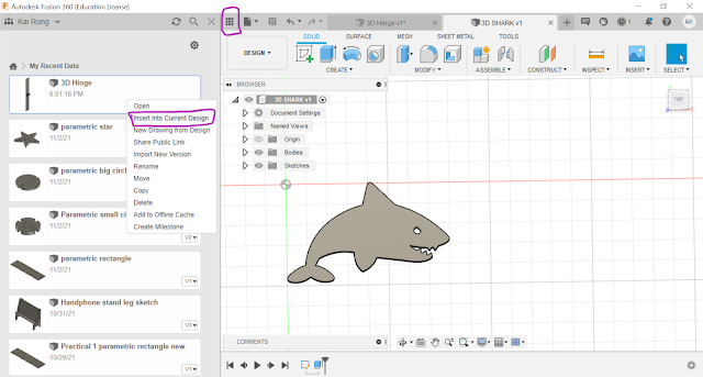
Drag and change the angle of the hinge such that it fits in the shape as shown below. Then right click the Hinge and click copy. Using the Ctrl - V on the keyboard to paste.

Add as many hinges as you would like and fit it into the shape.

Select all the hinges and right click and select Break link

Select the combine function, selecting the target body as the shark shape highlighted in blue and tool bodies as the 6 hinges highlighted in purple; operation as cut.

Select the Combine function, select the target body highlighted in blue and the tool bodies highlighted in purple. Remember to tick the keep tools box.

Do the same for the rest of the hinge joint (Blue for target body and Purple for tool bodies).

You can right click and select repeat combine before selecting the target and tool bodies.


c. Keychain hole (Additional Part)
Create Sketch and select top plane. Draw a 8 mm diameter from the tail of the shark


Extrude the inner circle by 10 mm, operation as cut

Extrude the outer circle by 2 mm

This is what the finished design in Fusion 360 looks like

3D Printing the Object:
a. Slicing the stl file
Right click the file name and select save as mesh. Click ok and Save.

Open Cura Slicer and open the stl file. Ensure that the printer selected is the desired printer and printing settings are set then click slice.
Link:STL file

Cura Setting used:
Printer- Creality Ender-3
Layer Height- 0.2 mm
Wall Thickness- 0.8 mm
Infill Percentage- 20%
Bridging and Overhangs- None
Supports- None
Bed adhesion- Skirt
Print Speed- 50 mm/s
Printing Time: 59 minutes
This is what the 3D printed object looks like


Why it cannot be easily made subtractively?
Additive manufacturing is the process of adding successive layers of material to create an object while subtractive manufacturing involves removing sections of a material by machining or cutting it away.
This object consist of a cross sectional hinge joint where there is a thin rod holding each individual part that is enveloped in a hoop shape connection to the next joint. It is difficult to carve out or cut away to produce this desired shape. Hence it cannot be easily made subtractively.
Reflection
The main objective of this activity is to design and 3D print an object that could not be easily made subtractively. This activity allows us to further build on our CAD skills learnt previously when designing a keychain or an handphone stand. It also took us on a refresher on 3D printing settings which we had learnt before in the previous semester in ICPD. This was a good activity to refresh our memory on 3D printing which most of us would have forgotten and allow us to use the skills learn in further sessions for example when prototyping a chemical device.
For this activity, I wanted to challenge myself to make something more advanced. I did alot of research and found many different objects that cannot be easily made subtractively but I had to keep it to a maximum of 1 hour printing time so I could not make something that was too complex. So instead of designing a simple door hinge, I decided to design a flexible animal consisting of many hinge joint that would allow the animal to "move" or slither like a snake.
When designing the object in Fusion 360, I faced many obstacles like clicking the wrong button which caused an error and I had to redo the designing many times. This made me feel annoyed and frustrated throughout the journey but I persevered on and did not give up and finally managed to designed the object. There was also a lack of resources to design my object so I had to find alternative ways for example when joining the hinge joint using the joint function, I had no idea how to do it so I refered to a ordinary door hinge tutorial and managed to understand how to do it. When designing in Fusion 360, I learnt many new shortcuts such as being able to upload SVG images instead of drawing the image manually by hand.
When 3D printing the object, I was worried about the time as I had only booked 1 hour and my printing time was 59 minutes which gave me no room for error. Looking around many of my classmates had many problems when 3D printing thier objects or problems with thier final print, so I was afraid that my final print would not function the way it should. However, patiently waiting during the printing, I could see layers slowly building up that shaped the object which was very interesting to see. The object printed out smoothly and had no issues, so I was very proud and satisfied with my work.
This task is important as it not only builds on our CAD skills but also on how to 3D print and serve as a refresher for 3D printing settings learnt previously. This would be useful in future sessions when we have to designing and produce a chemical product.
I used to think that 3D printing would be very difficult and complex because I thought that there would be many steps taken before an object can be 3D printed. However, after going through this activity, now i think that 3D printing is actually not that complex as all I have to do is to design in fusion 360, convert the file to stl and upload into cura slicer, change the printing setting and click slice then transfer the file to a 3D printer and the object would be 3D printed. So next, during my free time or school holiday, I can 3D print objects to try out for fun.

Comments
Post a Comment